Splat Board
Contents:
- Splat Daughter Board - September 2020
- Overview - The General Principal
- Schematic and Settings
- Installing the Neo7 GPS Module
- Add a Serial Console Port
- Installing a Speaker
- Antenna Recommendations
- AToD packet Processing
- The Anal3 Utility
- Schematics
[Top][Home]
Splat Daughter Board - September 2020
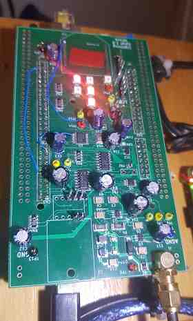
In 2020 development has been sritched to the Splat board.
KiCAD CAD files are also on github for the Splat board.
Plug the Splat on to the STM32 it can be a bit tricky getting all the pins to line
up causing it to skip a socket.
The latest firmware is archive my12 on github and we are using the newer STM32CubeIDE
v14 (the latest) as the development platform these days. The STM board will also
want to update its debugger firmware to the latest, and it needs that.
If you find the my12.bin binary file in the repo you can just copy that onto the
STM board using the debugger's USB file share capability. It will take the file
and then reprogram the board just by copying the file over. That way you don't
even need the IDE.
[Top][Home]
Overview - The General Principal
The Splat samples the RF input at about 2.7Mega samples per second into 12 bit values.
When the algorithm detects that there is a transient in the sampled data it sends the packet off
to the server so the server can look for coincident 'triggers' from multiple
detectors. The server also knows the precise location of each detector, so it
can work out the relative time of arrival of the same signal between detectors.
And then it can work out where the signal (lightning) strike location.
[Top][Home]
Schematic and Settings
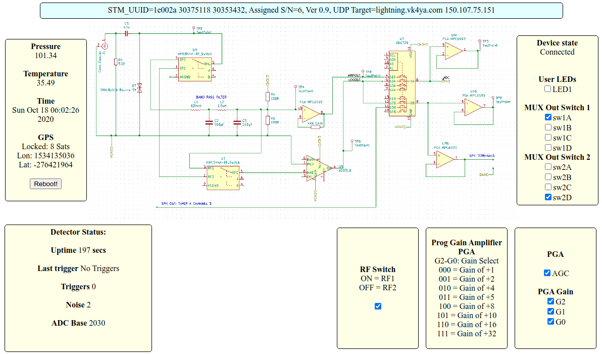
[Top][Home]
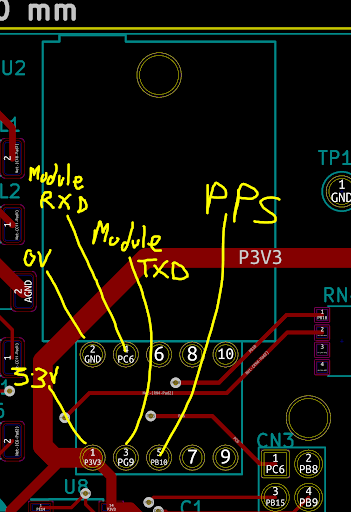
Installing the Neo7 GPS Module
The Neo7 and antenna must be installed.
Electronic-Devices/GPS-Devices/Neo-7.html
[Top][Home]
Add a Serial Console Port
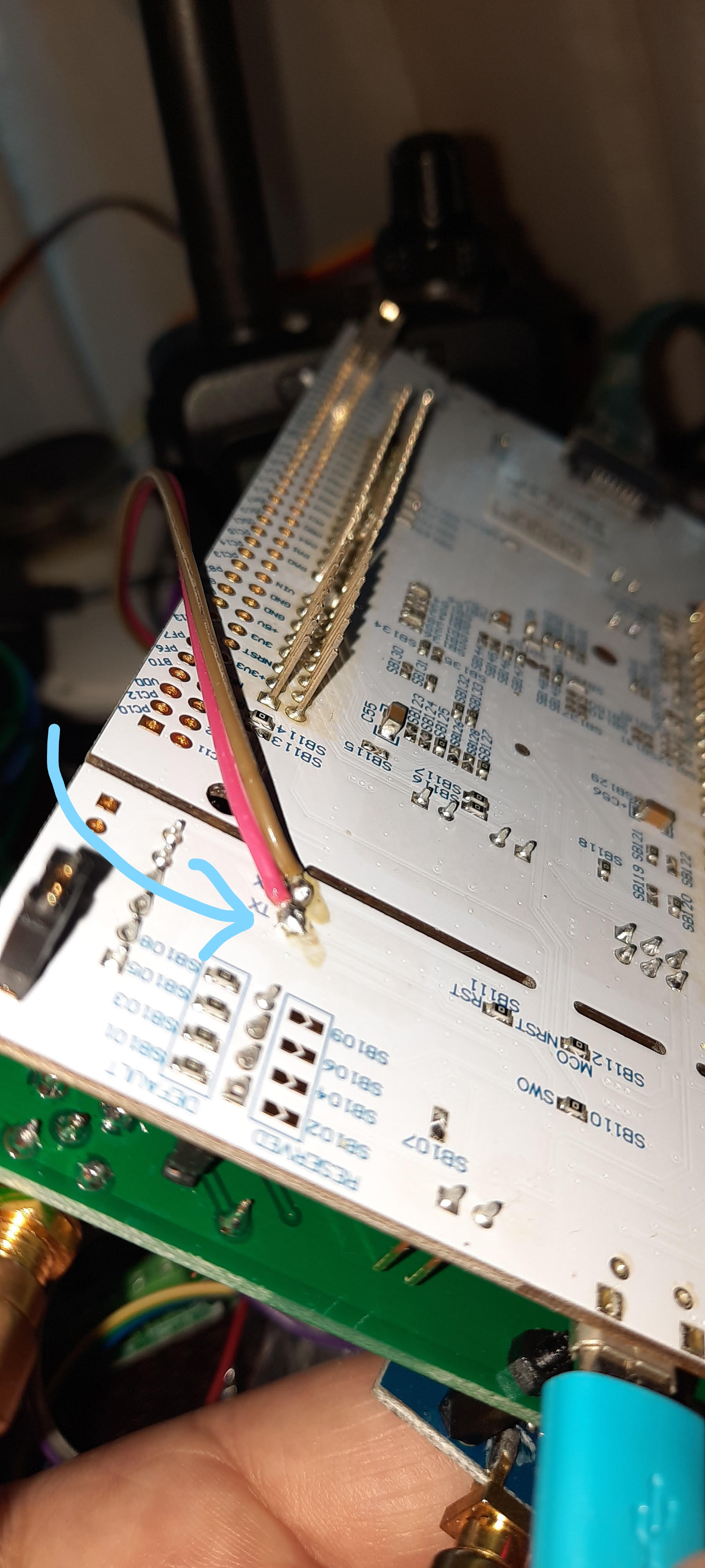
It is desirable to add the serial port console to assist in doagnosis and operation.
Solder two of jumper wires from the underside of the STM debug board's serial port
to the floating jumper wire sockets that plug into the middle two pins marked
'SER' on the Splat board. With the Splat board in position there is not enough
clearance to use jumper wires into the serial pins on the STM board.
The KiCAD CAD files are also on github for the Splat board.
(You should already have the debug serial port connected across the STM board
using jumper wires from the last incarnation of the project.
[Top][Home]
Installing a Speaker
There is also a mini-speaker header which produces zapping sounds
(PCM Synth from the onboard DAC) when the board triggers.
The speaker is connected to the header pins labeled LS1. The posative pin is on
the righthand side. I installed an 8 ohm, 0.3 watt speaker.
[Top][Home]
Antenna Recommendations
Best results are from a HF antenna (switch over to it when not using the radio),
but almost antenna will do - a simple dipole,
or a simple dipole running along the curtain rail.
Its terminated in 50R.
Inside antennas are best to stop lightning getting into your shack however,
sensitivity is well down for most inside antennas
You can use a 1:1 balun, but its not essential. The STM GND will go to the coax outer,
but its really looking for a potential difference as an input so the 'dipole' could
be one wire from the coax center as the shield will be at ground.
The length isn't really important either. It can be a few meter to 6 meters on each
side of the dipole.
A coax feed is best to wherever the antenna to prevent RFI noise entering
detector as the antenna passes close to electronic equipment in the shack.
[Top][Home]
AToD packet Processing
UDP Sample Packet:
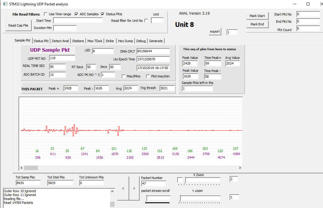
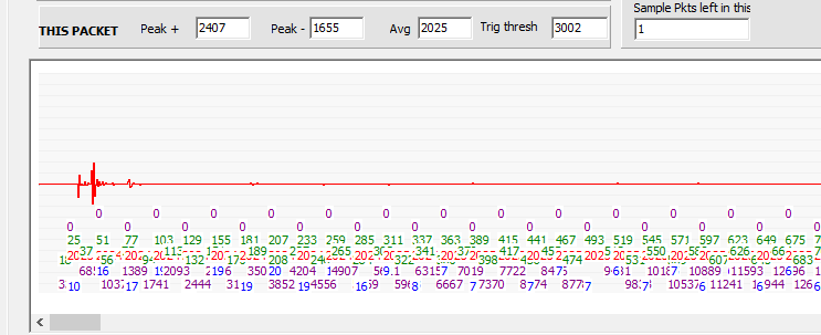
Zoomed Display:
In this zoomed display, the green is the sample number and the purple is the DMA counter.
The others are amplitude readings (mostly obsolete use these days in the Anal3 Utility).
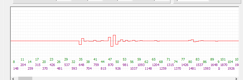
Zoom of Transient:
Expanded around that transient it looks like this:
[Top][Home]
The Anal3 Utility
This image shows how it simulates a strike (red cross) and where the
detectors are located.
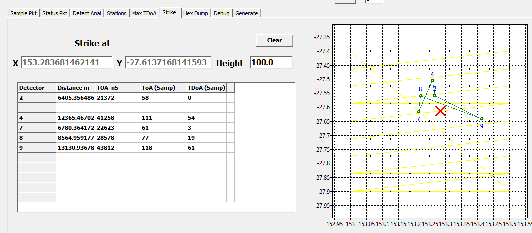
The Anal3 Utility's main purpose is to help with development and testing.
That app can simulate a strike and generate the equivalent packets to send to the
server and it can also read back the sampled data and display it, showing the
Lat/Long of their locations.
[Top][Home]
Schematics
Schematics
[Top][Home]
Glenn Lyons VK4PK
glenn@LyonsComputer.com.au
Ver:gnl20201028 - pre published v0.9