Cornell Dubilier CDR Rotor Model AR-22
Contents:
- Controller Label showing Model, Series and Serial Number
- Service Manual
- Schematics
- Wire Layout
- Parts
- The Initial Pulldown
- Initial Inspection
- Transformer Power Considerations
- Transformer
- Lamps
- Controlacitorler Capacitor
- Some Motor Theory- The Permanant Split Capacitor Motor
[Top][Home]
This is a description of the first stage of restoring a Cornell Dubilier
Model AR-22 Rotor and Controller. More to come when I have gathered some parts.
Thanks to the generous advise from members of the
Bribane Amateur Radio Club. In particular,
Ash VK4ASH, Bob VK4BXI, Graham VK4CEG, and Lin VK4VVK who gave me the project.
[Top][Home]
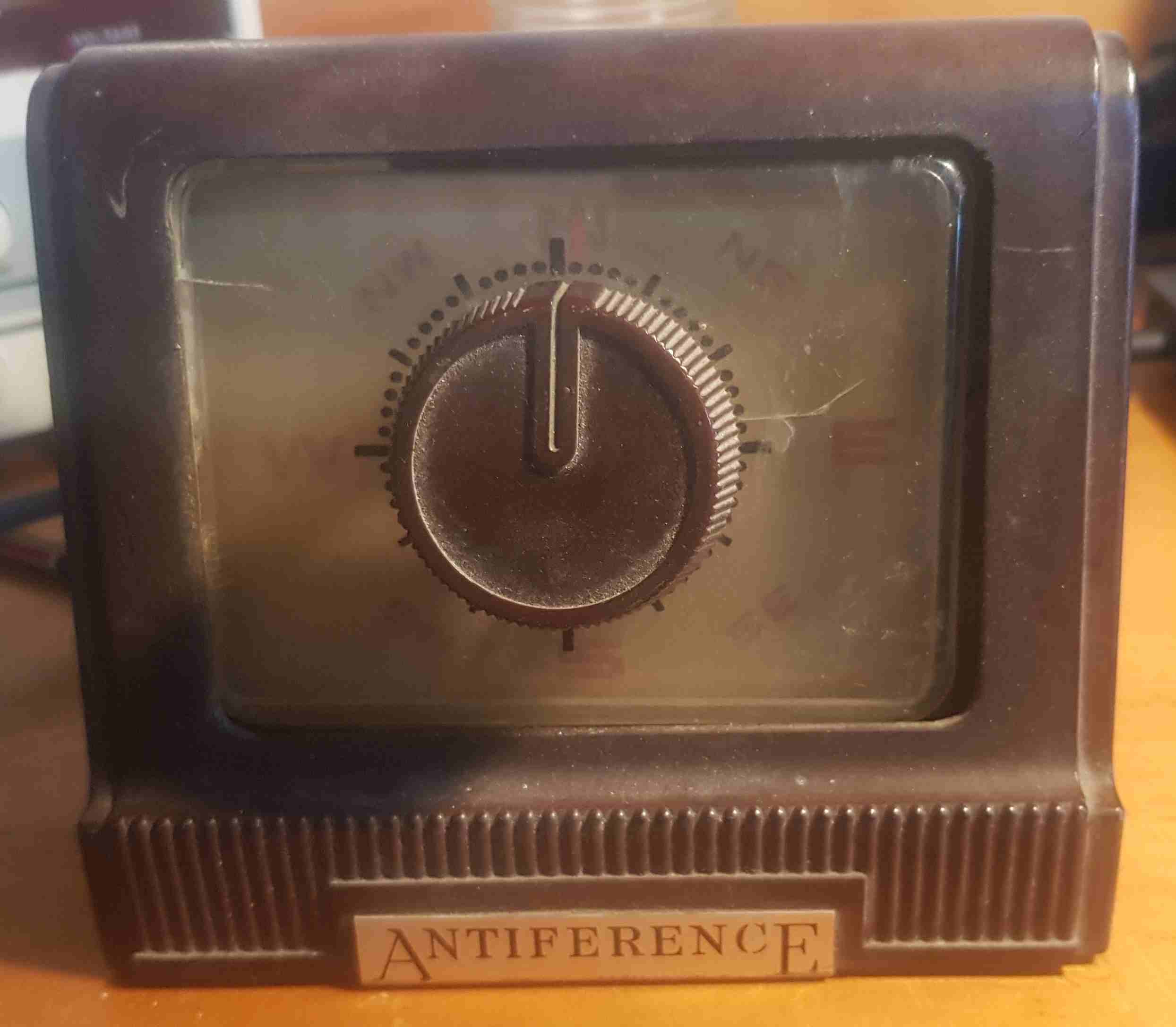
Controller Label showing Model, Series and Serial Number
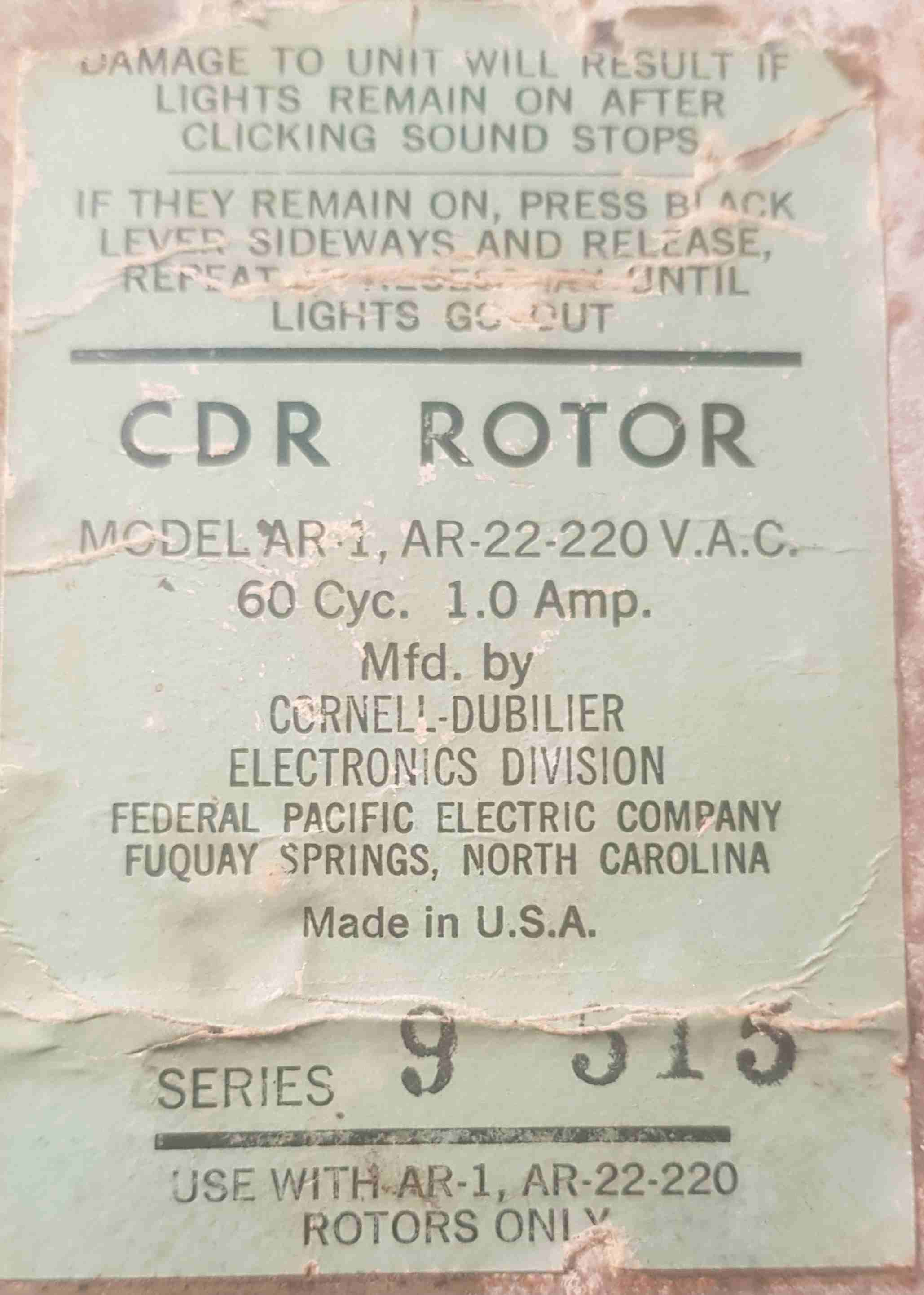
- Model : AR-1, AR-22-220
- Supply: 60Hz 1.0Amp
- Series: 9
- Serial: 515
[Top][Home]
Service Manual
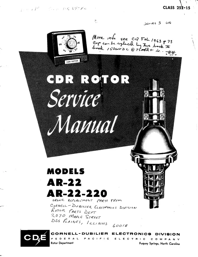
Cornell Dubilier Service Manual:
cornell-dubilier_electronics_ar-22_antenna_rotator.pdf
Source:
https://elektrotanya.com/cornell-dubilier_electronics_ar-22_antenna_rotator.pdf/download.html
[Top][Home]
Schematics
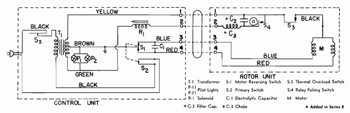
[Top][Home]
Wire Layout
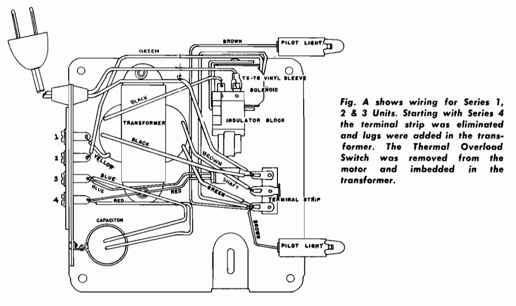
[Top][Home]
Parts
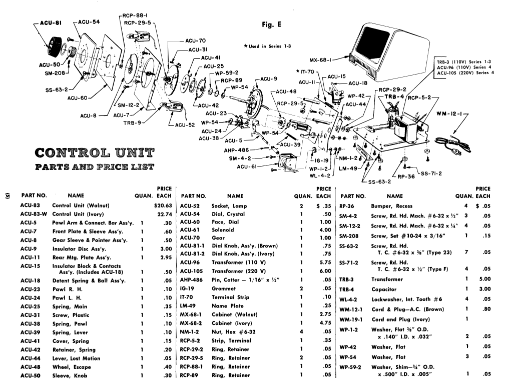
[Top][Home]
The Initial Pulldown
Controller:
Rotor:
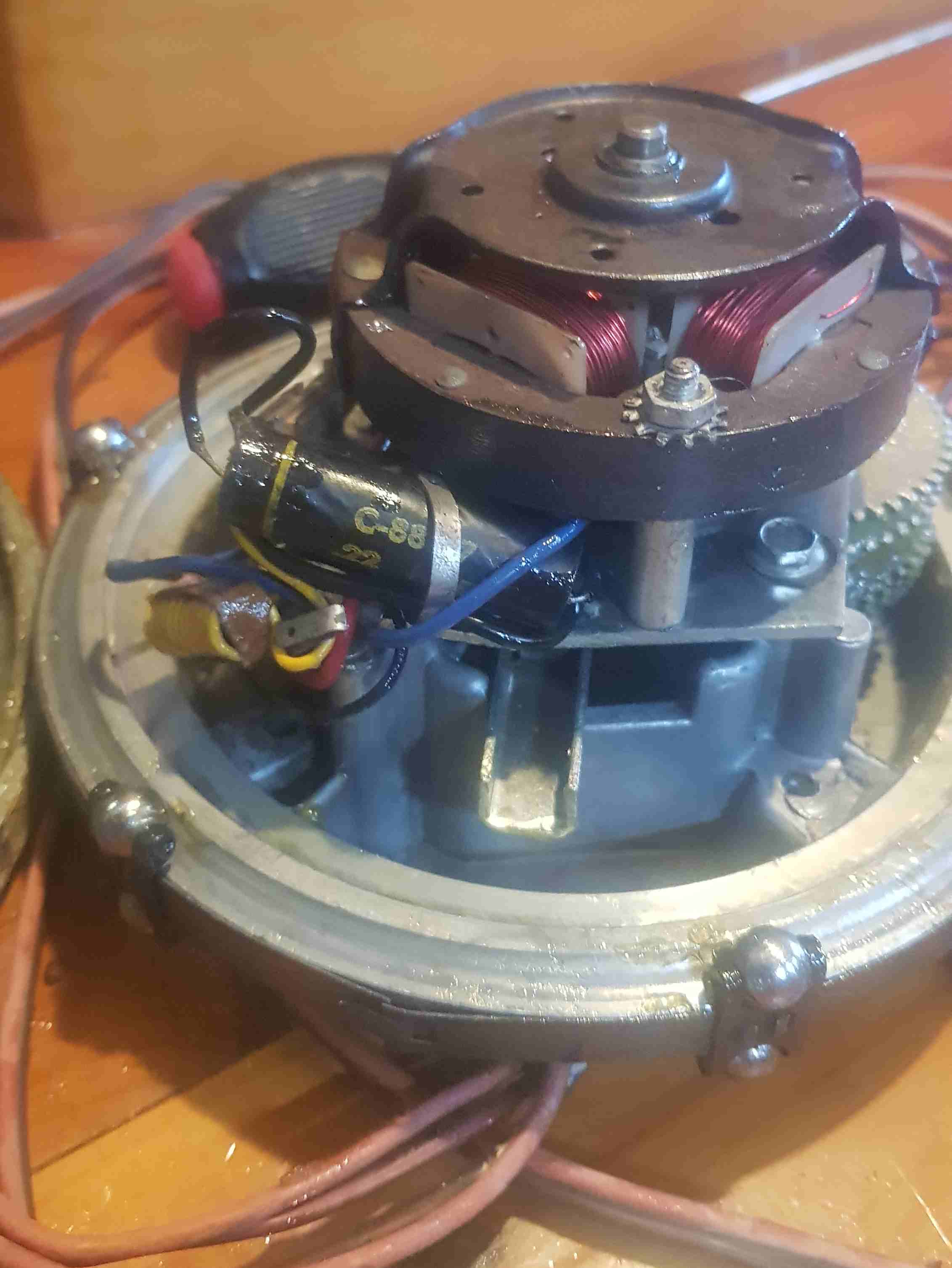
[Top][Home]
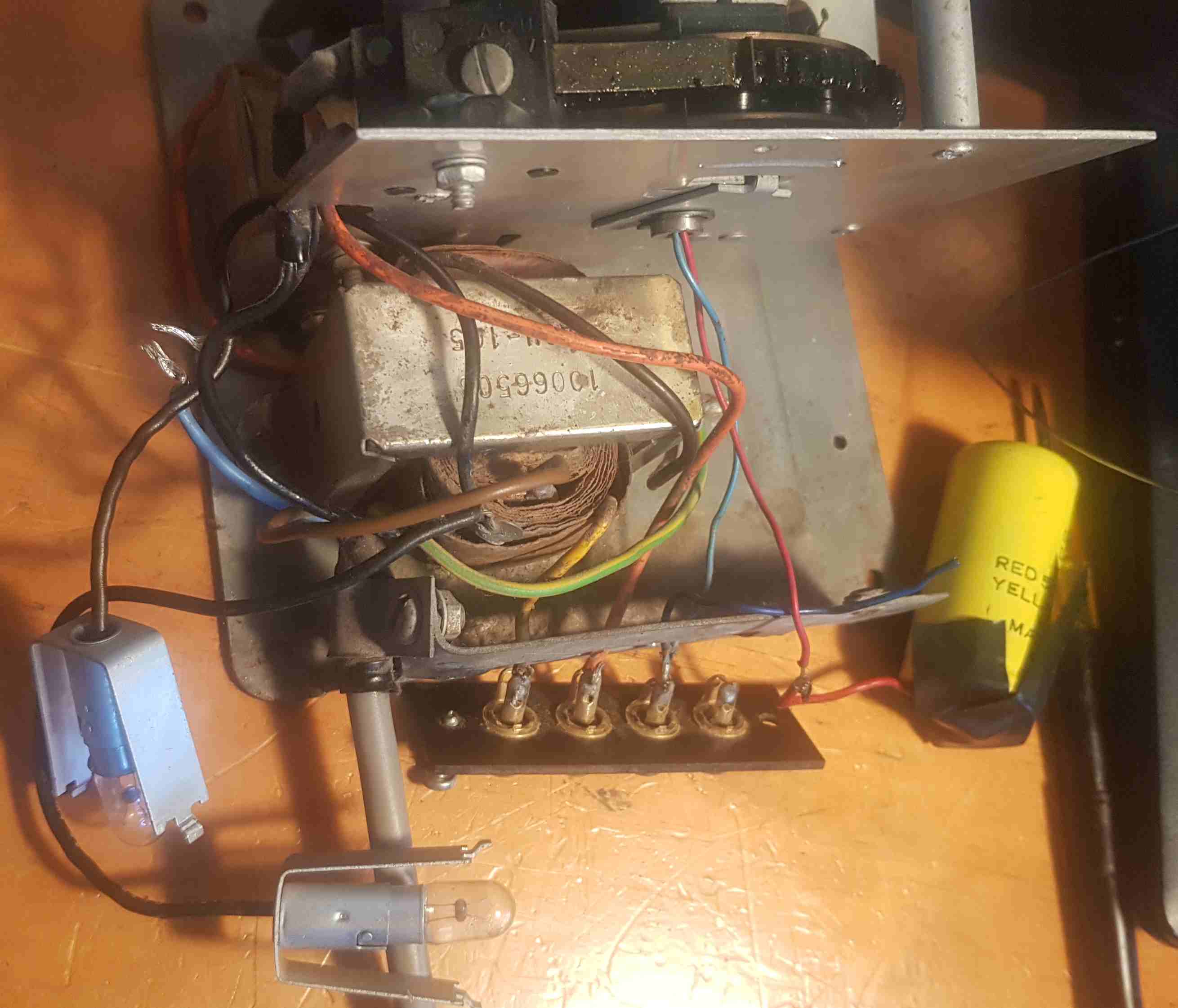
Initial Inspection
After pulling the cover off and cleaning off some dirt these are some initial observations.
- The unit is very old judging by the styling and Bakerlite case. Cicra 1940.
- No fuse was fitted. This will have to be rectified!
- The Transformer appeared to have Active (primary) shorted to Gound at mains voltages but
the resistance read okay on a DMM, so will require replacing.
More on the transformer below.
- The Yellow capacitor in the controller was lying lose in the case and the green wire
was broken off when I open it. This probably required for the crrect phasing to drive the AC motor.
- The 0.22uF and choke in the rotor, would be noise suppression. These should
require checking.
- the first requirement is to find a replacement 34VAC 100VA transformer, before
any mechanical clear up or repair.
- There are 4 wires coming down the tower,rotor to controller. The first pair
of these is probably CW and CCW rotation, and the second pair are for position
feedback.
- The cap in the rotor unit maybe suspect as well, its probably very leaky.
Or is that grease on it's surface?
[Top][Home]
Transformer Power Considerations
You can probably power the motors from a 24V ac transformer. Motors might be a bit slower,
but use good think wire to reduce the losses up the tower. You can probably use
use a simple DC/DC converter powered from a rectified 24v supply to do the direction
sensing. The motors will need AC for drive though.
If you add up the (DC) resistance in the drive side (4R + 0R75 + 2R5) gives 7R25.
Means that (very very roughly) the max current that can flow is 3.6A (at DC) but
trying to get an idea of sizing of transformer.. so 86VA, so see if you can find
a 100VA transformer? This is likely a very high over estimate given the size of
the transformer
12v plus 12v transformers are common. 2 * 12V * 3Amps or 80VA would probably
work well.
As it is an AC motor the volts won't matter too much (unless you have long lead
length to tower) The speed will aways be the same.....it is driven by 50 hz. The
motor cap is important to get right. In theory what you want is the same current
in both phases of the motor but phase displaced at 90 degrees. This is gets messed
up by the resistance of cabling to the rotator with different lengths and different
conductor sizing. In practise it will work some how, but the phase shift and how
well the two phase currents are balenced will determine how much torque the motor
will produce. So any volts from ~15 volts upward will work. If you are testing
with very short cable length currents will be high the motor will be noisy and
overheat quickly.
Note that both the transformer and the motor are short time rated, so I seem to
remember ~3 amps phase current X2 and ~20 volts so 60 VA continous but anything
over 40 VA would be fine (then the motor will burn out first !!)
It is probably okay to just match the "size" as I am pretty sure the power rating
is mostly the iron cross-section and the windings are then adapted to the outputs requried.
[Top][Home]
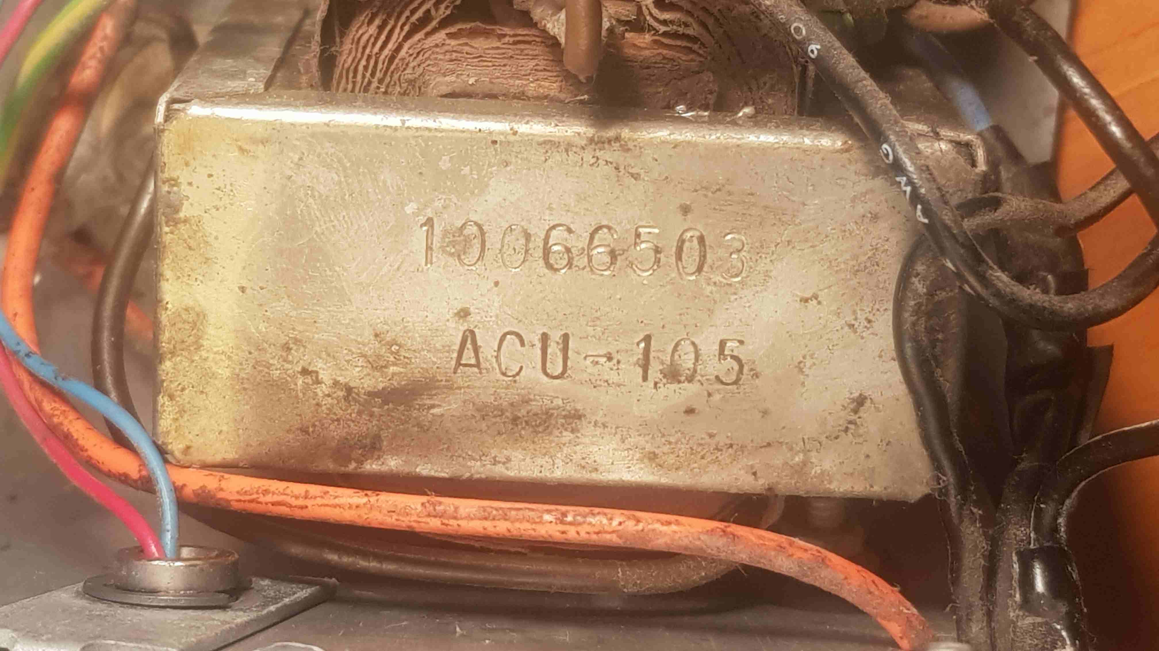
The transformer indentification 10066503 ACU-150 do not reveal any information
on Google, so I assume that it will be a custom transformer.
Diamensions:
- Length:58
- Width: 27
- Height: 50
- Hole centers on the foot is 71.5
- Weight: 550 grams
Taps:
- Ground - Black
- Active - Brown
- Neutral - Blue
- 6 VAC - Black
- 34 34VAC - Yellow
There is also likley a thermoswitch
included in the windings.
Looks like one tap only supplies the two 6v lamps. Lamps light on 6v on a test PSU.
By the schematic and test onstructions below the other tap is 354VAC and goes to
the rotor only. All the controller switching must be supplied on the return connecting wires.
To test the voltage levels, disconnect the control cable and with the A.C. line cord
plugged in, and the control knob turned to the right or Left of the red pointer, a voltage
check should show 34 volts A.C., between terminals one and the metal chassis and
6.5 volts A.C. between termina two and the chassis.
[Top][Home]
Lamps
There are two Lamps, one either side of the front bezel to illuminate the dial.
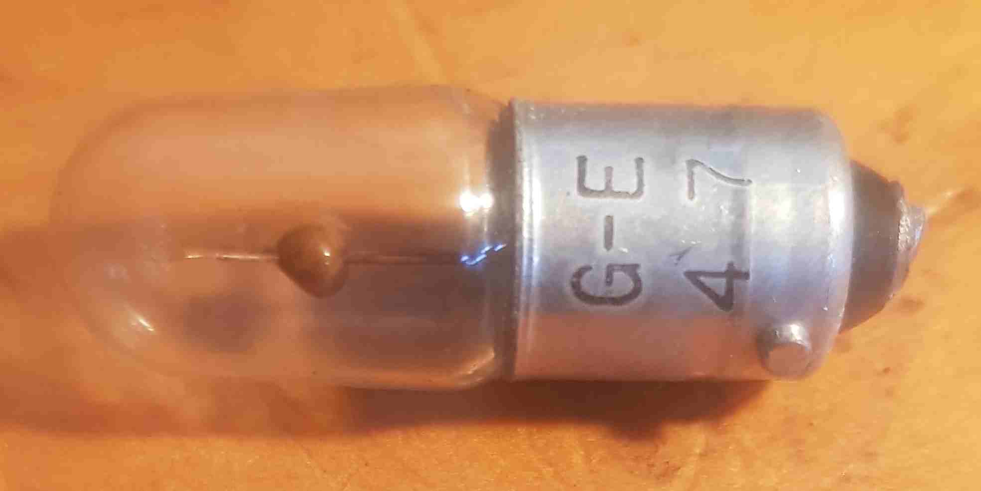
- Wattage: 1 watts
- Voltage: 6.3 Volts
- Lumens: 6 (1 Candle)
- Type: BA9S
- Base: Miniture SC Bayonet
[Top][Home]
Controlacitorler Capacitor
This a double capacitor in a single enclosure. It is likely essencial for
phase shift to drive the rotor motor.
- DUBILIER DRILITIC CT 1128
- RED 50uF 150V DC C/S
- YELL 50uF 150V VDC C/S
- BLACK Negative (Common)
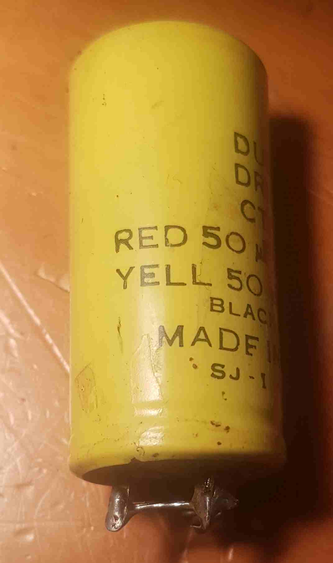
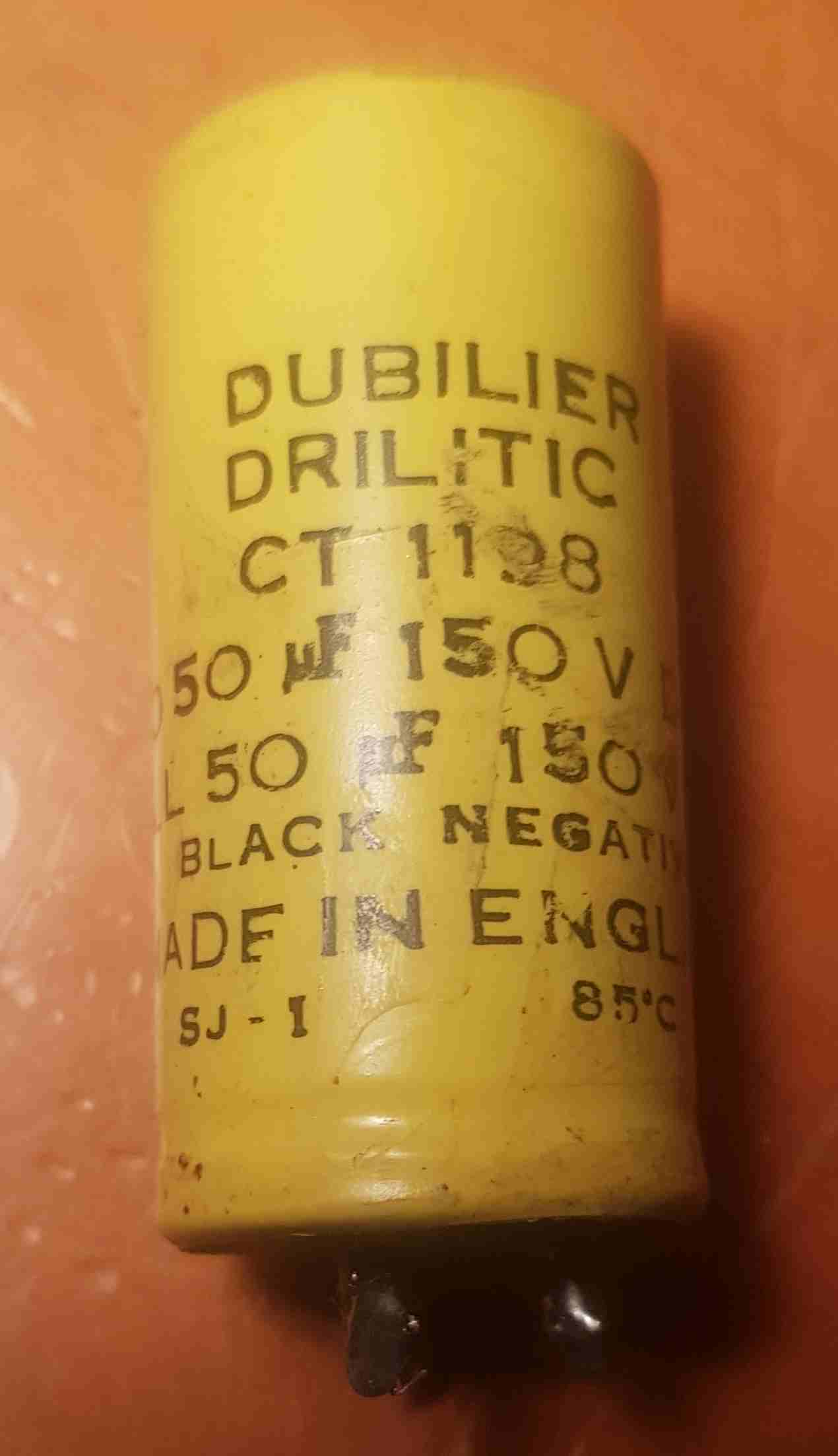
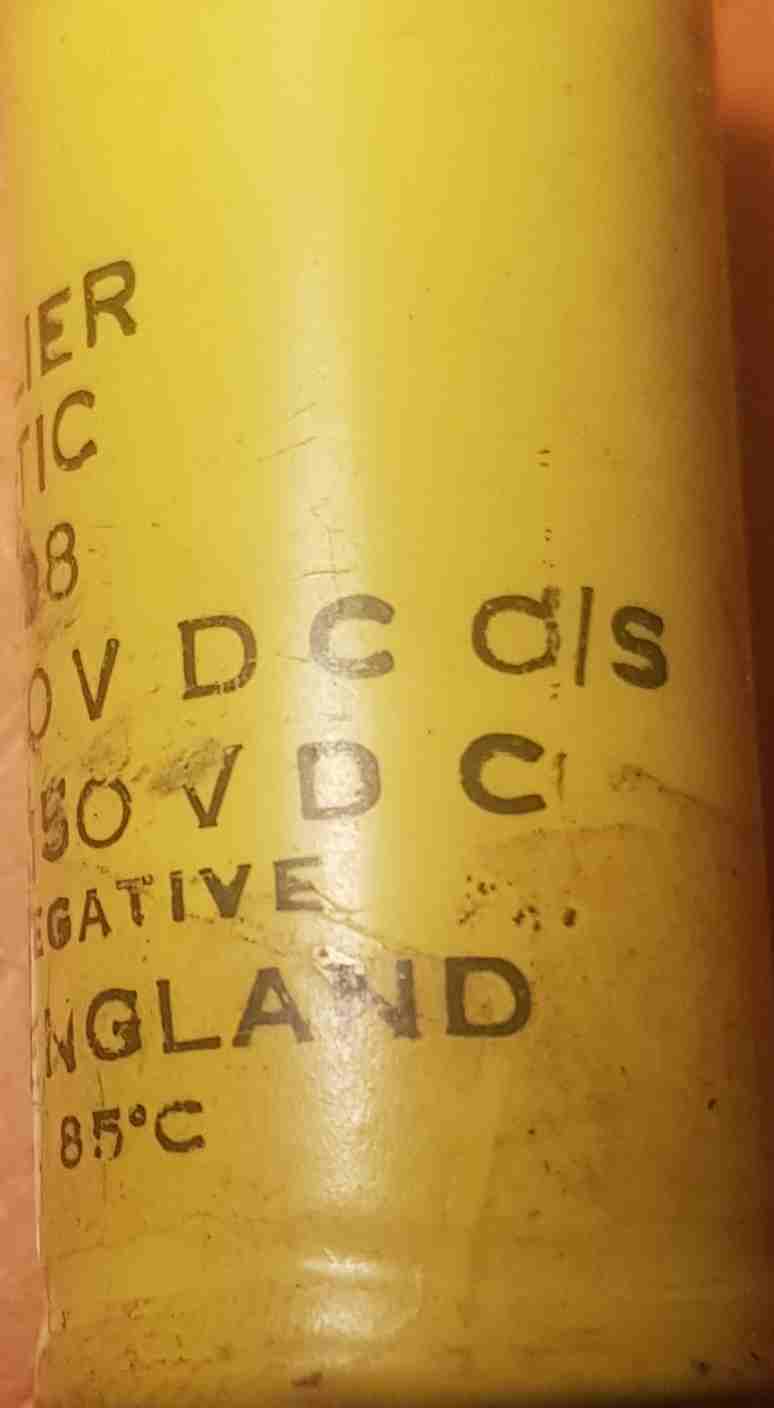
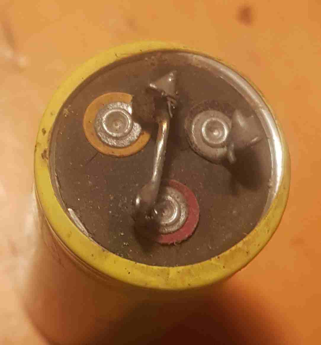
This capacitor may require replacing due to it age.
[Top][Home]
Some Motor Theory- The Permanant Split Capacitor Motor
Types of Electric Motors:
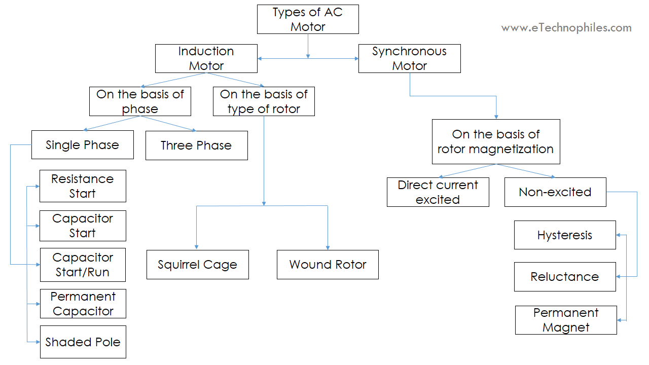 Source:
https://www.etechnophiles.com/types-of-ac-motors/
Source:
https://www.etechnophiles.com/types-of-ac-motors/
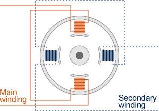
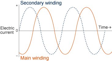
When the power supply is turned on, the current flows first in the main winding
and then, with a short delay due to the capacitor, in the secondary winding.
This difference in the main and secondary winding currents takes the form of a
phase difference (meaning their waveforms are offset from one another on the
time axis), causing the peak magnetic field to alternate between the two windings
and thereby generating a torque that starts the motor rotation.
This type of motor is somple but suffer from low efficiency due to energy losses
from heat generated in capacitor. Capacitor may need periodic replacemnt. They
also tend to be noisy and chatter as it is difficult to maintain the optium
phase shift.
Source:
https://www.aspina-group.com/en/learning-zone/columns/what-is/008/
[Top][Home]
Glenn Lyons VK4PK
glenn@LyonsComputer.com.au
Ver:gnl20220926 - pre published v0.9