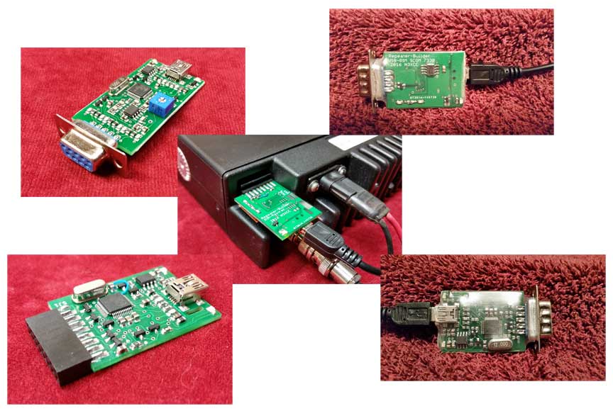
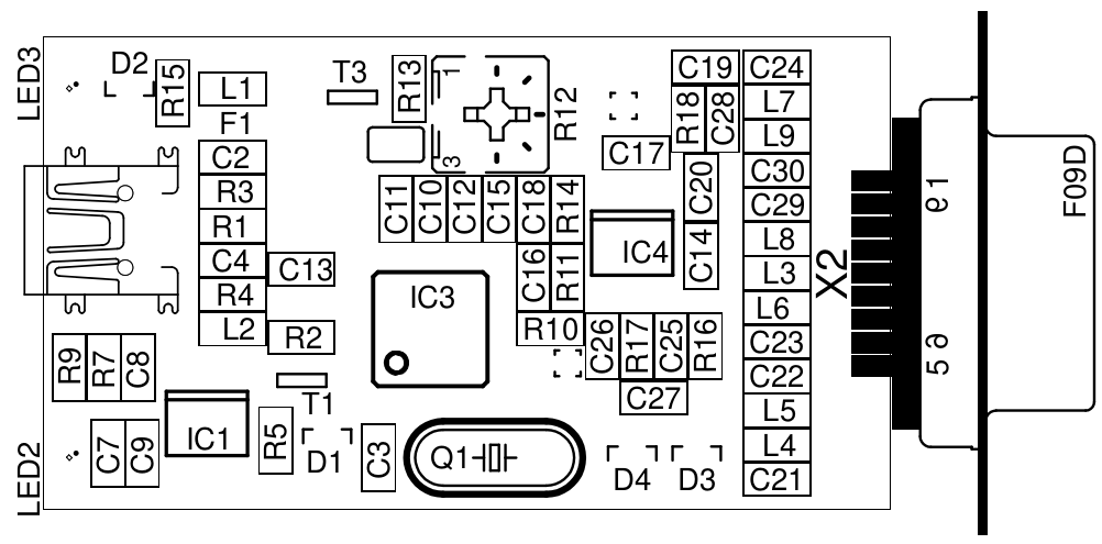
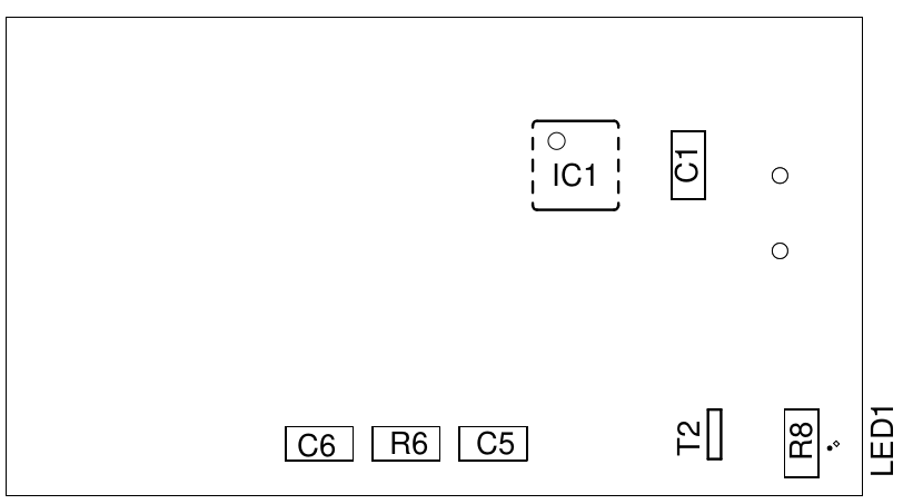
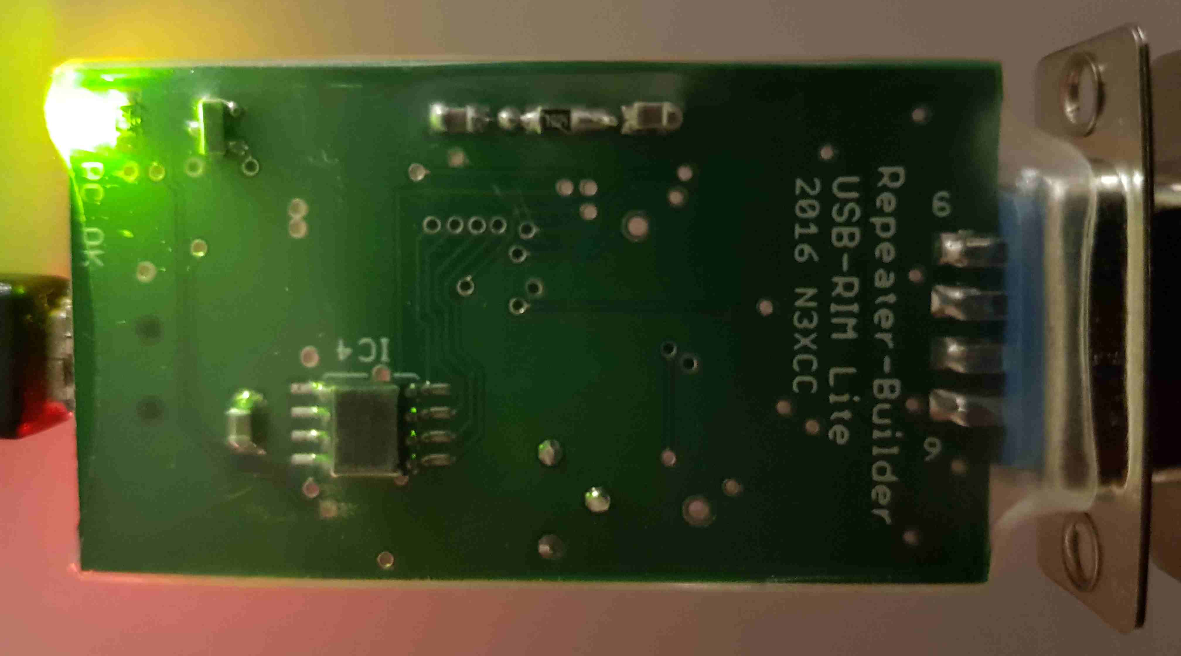
Repeater Builders's RB-RIM-Lite
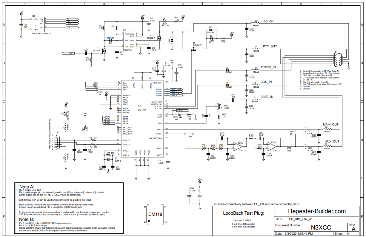
This Radio Interface Module is based upon CMedia's CM119 USB Audio Controller
Features: (note that the Lite version does not have all of the features that the "full-blown" RIM.)
Instead of two channels of low-pass filtering, the RIM lite only has one.
Typically only one channel of filtering is needed since there is only ONE modulator
in a given radio. This filter remains 5 pole with a "knee" of approximately 10kHz.
The charge pump and additional amplification stages have been removed to reduce cost.
This module still makes over 1Vp-p of audio which is adequate for driving most modulator
circuitry directly.
The buffering of the COS and CTCSS inputs has been reduced to a simple diode.
Again reducing circuitry that is not often used.
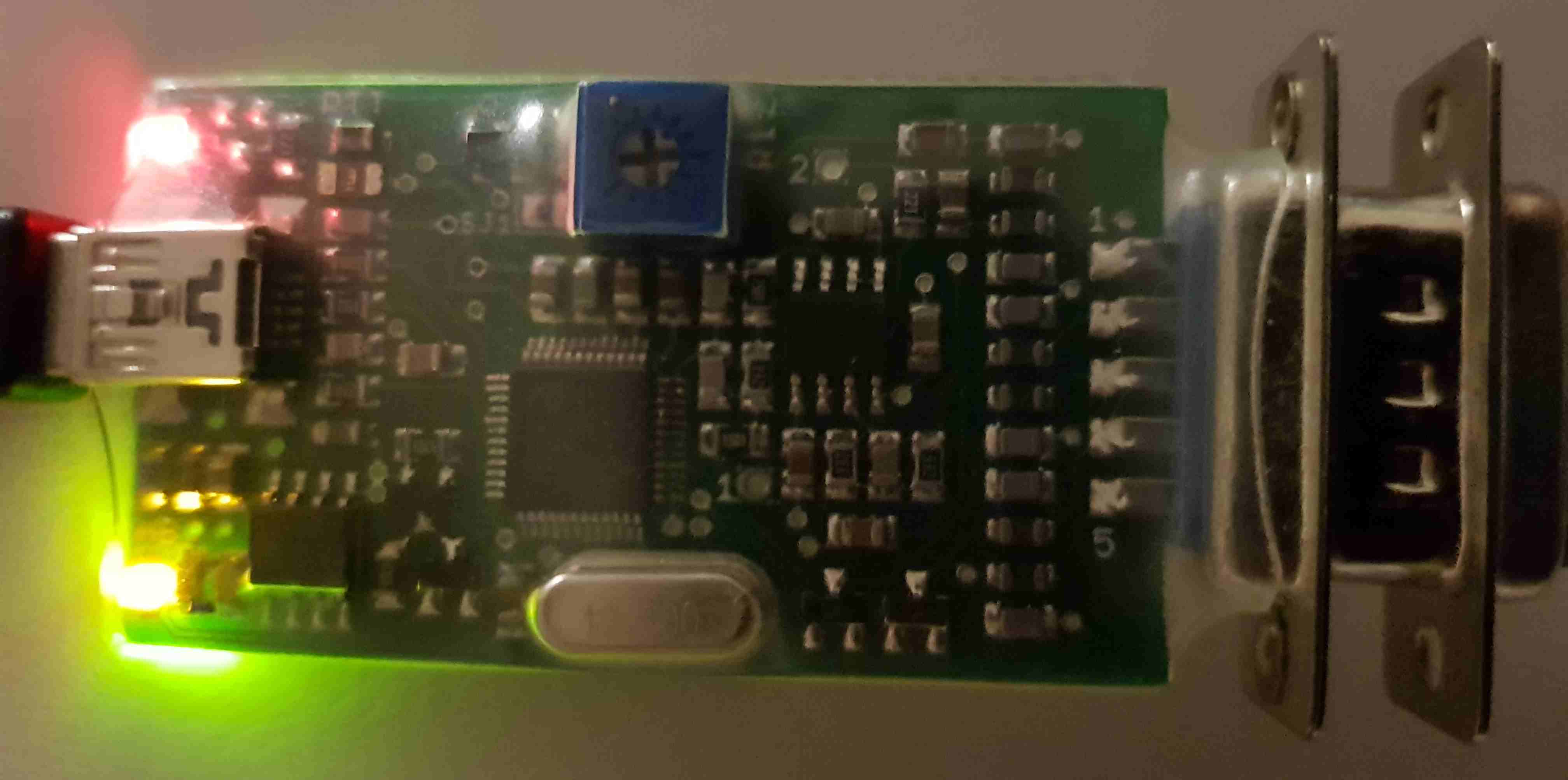
The discriminator audio input attenuator is now a potentiometer. No more external voltage
dividers necessary to knock the radio's audio down to the CM119's input level!!
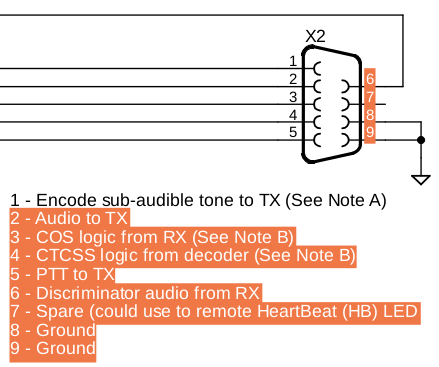
The DB-25 connector has been replaced with a DE-9. This simplifies connectons and reduces
product size. This means that the additional I/O pins are not brought to the outside world.